TestED: Deyard USB CAR CHARGER (4 Port, 48W 9,6A)
This is a translated version - for the GERMAN version klick here...
Frist thought as i got the product offered for testing: "please not another car charger!", but as the technical data looked quite good i decided to give it a try. I was a little reminisecent of the "iclever" charging adapter i recently dismanteld (this seems to be variant created later from the same base).
Too long - didn´t read (tl;dr):
I liked:
Overload protection / short circuit protection
very low standby consumption (about 5mA / 0,060W)
quite adequate voltage regulation
2 voltage converter circuits (2 ports on the left / 2 ports on the right)
blue power led
efficiency of about ca 89% (23W load @ 12V)
quite solid aluminium front cap
to be improved:
Overload protection does not reset by itself
Only one LED (but 2 circuits)
In my opinion... That´s - so far - the best car charger i ever had on my testbench. Period. Efficiency as well as standby consumption and heat dissipation meet my expectations.
All experiments and setup are equal to the previously tested variant (see link). Voltage stability looks OK. Temperature stays quite low - even when loaded with 23W for 2 hours.
A few tests later it came to my mind why that´s the case: The device uses two separate voltage regulators. Which seems to dissipate the heat more equally. Even the overload protection is split between the two circuits (but doesn´t show on the control LED - as there is only one).
In my long endurance test (1h) one circuit had to deliver 2,808A @ 4,81V, the other 2,067A@ 5,04V. Summing up this results in an efficiency of about 89%.
Output Voltag @1A Load
Temperature with maximum load
With my new USB load resistors just having arrived, i tried to destroy the little gizmo: 3 ports are loaded with about 1,95A each. Resulting in about 43W power drawn from the USB ports (the 12V power supply delivering 49,6W) - thus resulting in an efficiency of about 87%. I stopped after 5 Minutes as my cables started to melt (have to cool the resistors in the future).
Hot stuff
The 12V power supply shows 49,6W (added up)
Teardown
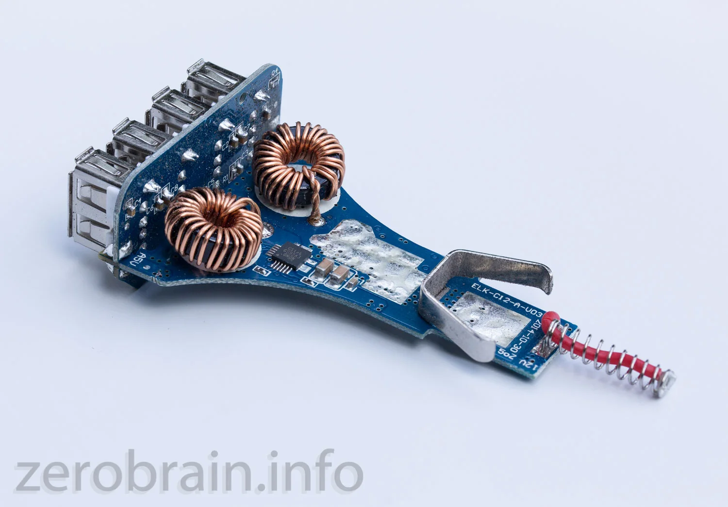
That aluminium cap really gave me a tough fight. Pretty solid thing. The inner values look quite similar to its´ smaller "iclever" brother. Just with the power split between two circuits (using an GStek "GS92A3" chip). Again we see the red wire soldered into the spring to reduce resistance and two solid ground contacts on the sides. Datecode shows this device was developed 3 months after the smaller one.
.


